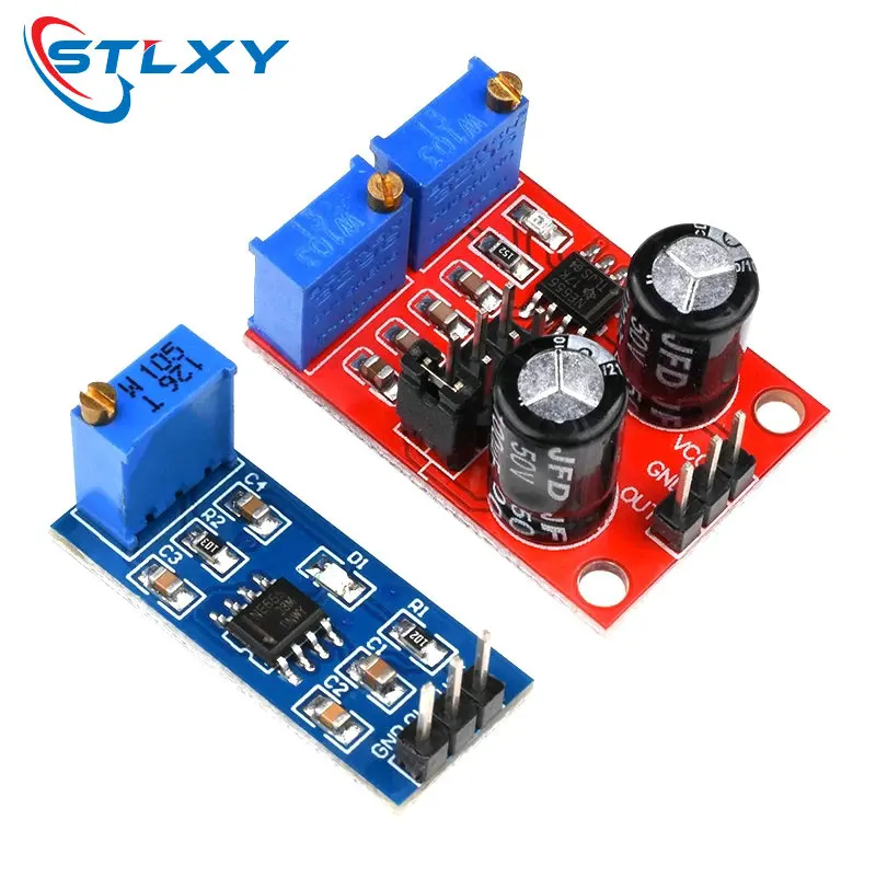
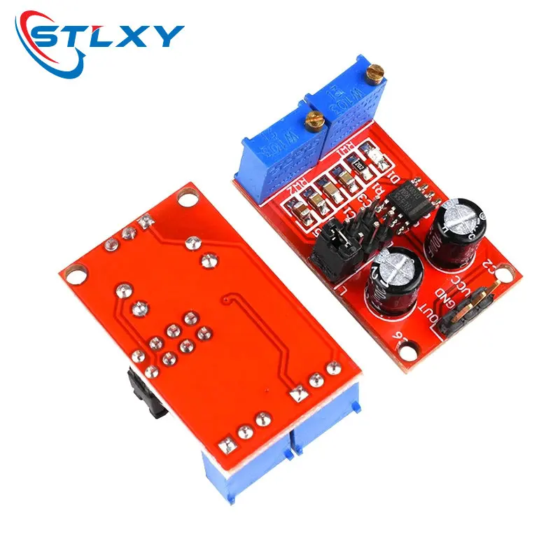
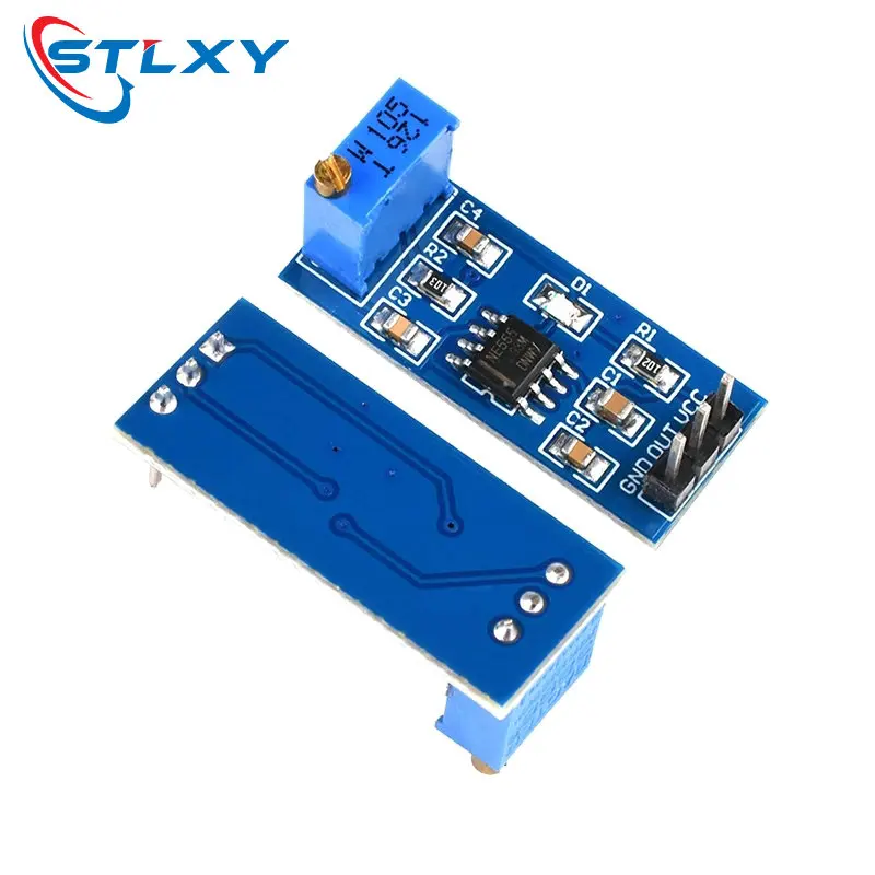
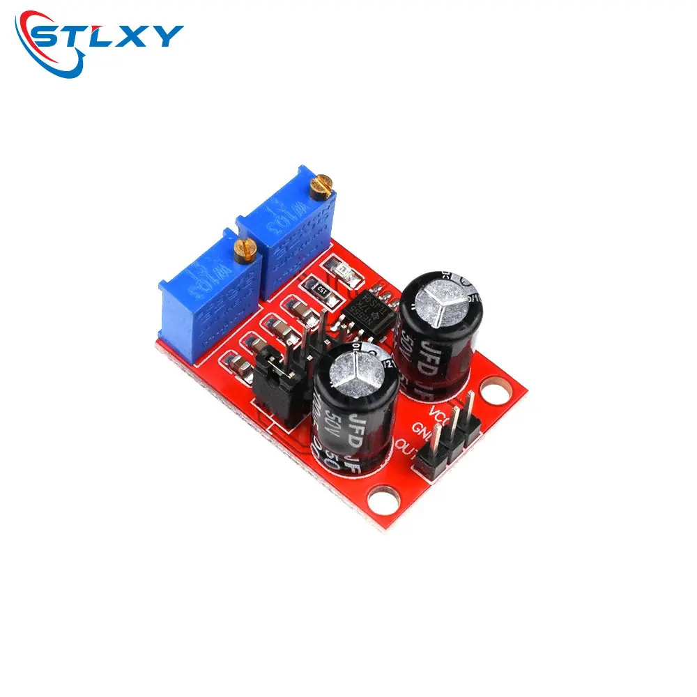
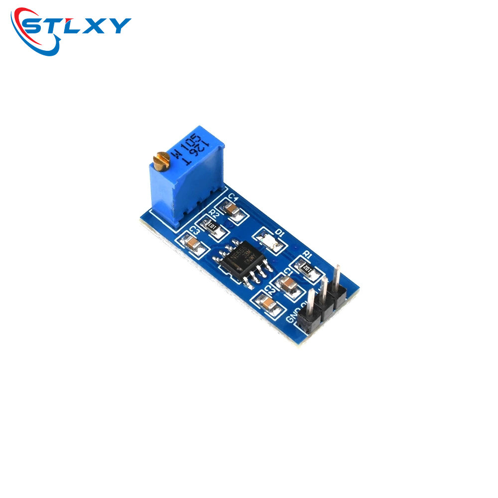
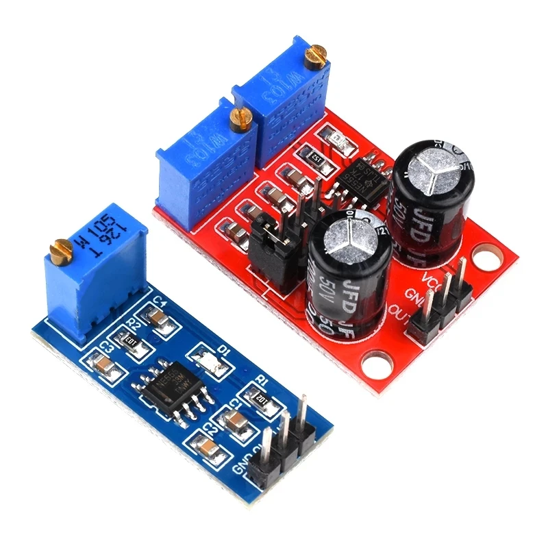
NE555 Pulsfrequenz Duty Cycle Einstellbares Modul Rechteckwelle 5V-12V Signalgenerator
Onboard NE555 IC. 2. Single channel signal output, the output duty cycle about 50% square wave. 3. Plate load resistor, adjust the resistance to control the output frequency. 4. Onboard power indicator. 5. Working voltage: 5V~12V. Size: 3.1CM * 2.2CM 1, the main chip: NE555; 2, Input voltage: 5V-15VDC. 5V power supply, the output current can 15MA around; 12V power supply, the output current can 35MA around; 3, the input current: 100MA 4, the output amplitude: 4.2V V-PP to 11.4V V-PP. (Different depending on the input voltage, the output amplitude will be different) 5, the maximum output current: 15MA (5V power supply, V-PP greater than 50%), 35MA (12V power supply, V-PP greater than 50%) The scope of this module: 1 is used as a square wave signal generator generates a square wave signal used for experimental development. 2 to drive a stepper motor for generating a square wave drive signal. 3 adjustable pulse generated for use by MCU. 4 adjustable pulse generation, control circuitry associated. Advantages: 1, the output with LED indication, there is no output straightforward (low LED volume, high LED off frequency is relatively low, the LED flashes); 2, the output level selectable frequency range, the output frequency is more continuously adjustable; LF file: 1Hz ~ 50Hz IF file: 50Hz ~ 1kHz High-frequency file: 1KHz ~ 10kHz HF file: 10kHz ~ 200kHz 3, the output duty cycle can fine-tune, duty cycle and frequency is not separately adjustable, adjusting the duty cycle will change the frequency 4, the output frequency is adjustable; Period T = 0.7 (RA +2 RB) C RA, RB is 0-10K adjustable; Low profile when C = 0.001UF; IF stalls C = 0.1UF; High-frequency file C = 1UF;